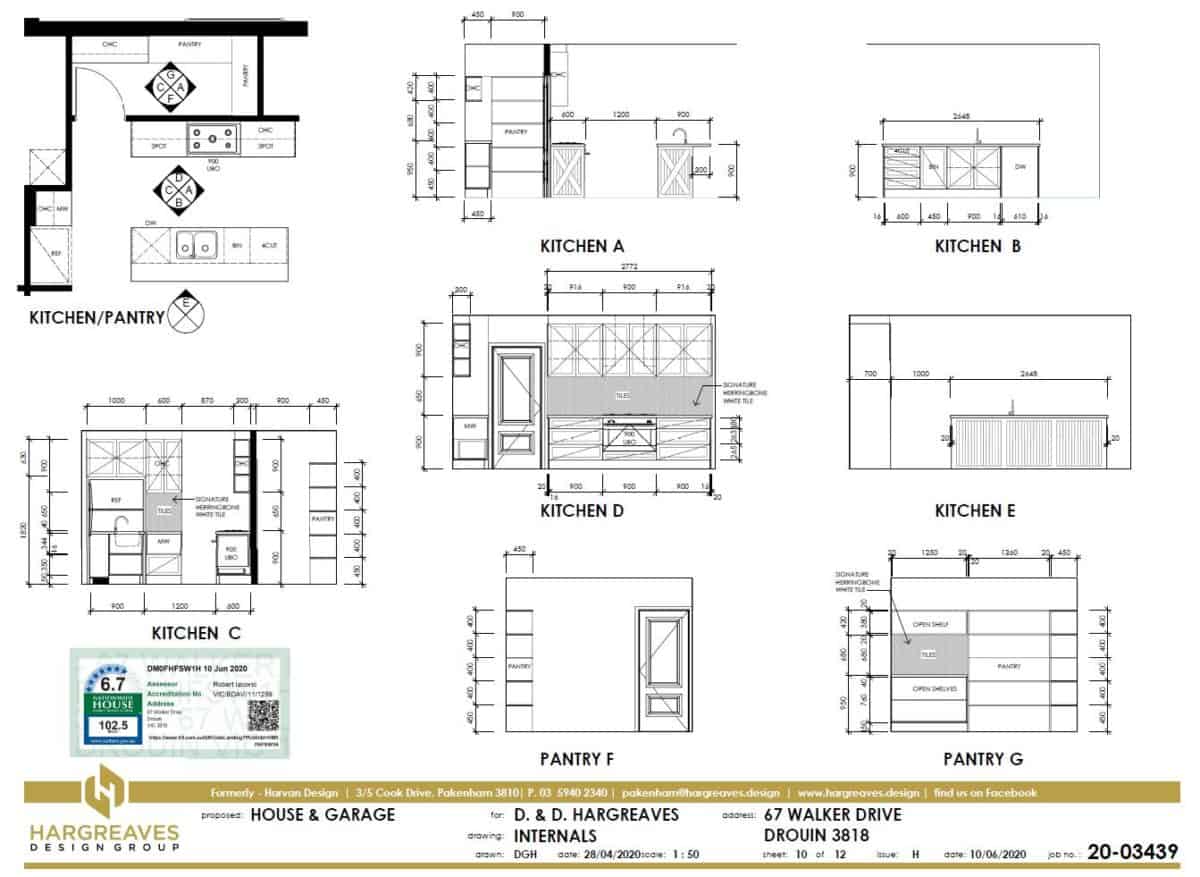
Internal Elevations

Cabinetry Details


The ‘Internal Elevations’ sheets are ancillary to the main working drawings set. They are not required in the minimum working drawings set to gain a building permit. They are, however, requested often in order for our clients to be able to visualise the internal cabinetry items in their wet areas.


Useful for accurate quoting


If you are having plans done in order to get quotes from a number of builders, it is always a good idea to have internal elevations of your wet areas & cabinetry done. This way each builder will be pricing the same cabinetry details & comparison of quotes is much more relevant.


Walk in Robe Fitout Details


With the wide array of tiling choices available today the detailing on this sheet can make sure mistakes are not made due to the tiler doing what he thought you wanted. Having these sheets as part of your set also helps remove necessary clutter on the floor plans trying to cover cabinetry details by notes. Most robes & walk in robes are fitted out these days & the detailing should be particular to each client’s needs.

The Floor Coverings Plan

Carpet, Tiles, Timber & Laminate


The ‘Floor Coverings’ plan identifies the different floor coverings in each room of the house. This is mainly required for the completion of the 6 star energy rating which takes into account the different thermal properties of each floor covering.


Areas for quoting


The areas shown are accurate & allow clients to order their floor coverings with accuracy. You will find, however, that the flooring suppliers won’t trust the figures shown & will still measure the plan with a ruler to estimate their own areas to allow for wastage & cutting.


Slab Recesses


Depending on the flooring chosen a rebate in the slab may be required to ensure there are no tripping hazards where different coverings meet. These plans indicate tiles through the shower recesses which will mean a 50mm recess in the slab to create fall to the drainage point.

The Electrical Plan

Fitting & fixtures


The ‘Electrical Plan’ details the electrical fixtures & fittings placed in your house. All power points, light fittings, TV points, data points & switching for lights are shown on this plan.


Maximum Wattage Allowed


Also required is the total number of light fittings & their wattage to ensure the total wattage complies with the building regulations. This is indicated by the ‘Artificial Lighting Table’ which shows the maximum wattage allowed per m2 for each area of the house.


Heating & Cooling


Ducted heating points are also shown either in the ceiling or floor depending on the style of house. Location of the heating unit in the ceiling is indicated close to the manhole. The return air & thermostat location is important as nobody wants a return air grille as a feature in their house.

Sections & Details

The importance of details


The ‘Section & Details’ sheet is the most unloved sheet in the drawing set. Clients mostly don’t understand it, builders sometimes overlook it & engineers can ignore it. However, the information on this sheet is very important for regulatory compliance & building inspections. It ensures the builder is using the right details when constructing certain areas of the house.


Details do vary


Most good builders will know exactly how to build the standard details shown on this sheet but they do tend to vary from builder to builder. Details of lintels over garages, for example, are constructed in several different way depending on the garage wall & roof structure.


Standard section only required


There may be one or more sections through the house depending on the requirement to demonstrate two or more construction techniques in various parts of the building.


External consultants


Whilst this sheet used to include slab edge beam, weep hole waterproofing & other standard details, these have over time been outsourced to engineers & other consultants who specialise in these areas & have the insurance to cover the structural design.


Timber framing schedule


The Timber Framing Schedule indicates all timber sizes to be used in the house. The caveat on this is that, if the wall framing is over 2.7m high, then the whole timber structure will need to be justified by a structural engineer.


Refer to the engineers drawings


Roof trusses are usually provided with truss computations from the truss company to justify their spans. Likewise, steel lintel spans to support brickwork over external windows & doors need to be engineers if the spans exceed those shown in the external lintel schedule.

The Elevations Sheet

How will your house look?


The ‘Elevations’ sheet is where our clients really start to understand what their house will look like when built. However, sometimes this sheet can be misleading. The idea of detailing elevations is for each orientation of the house to be notated & dimensioned externally. The misleading part is you have to be omnipresent to see it this way.


Don’t be fooled


The elevation assumes that your eye is perpendicular to all points of the building at the same time. The only time your windows will look symmetrical, or centred under the ridge, is on the elevation because on site your eye will never see it like this in real life.


Compliance Profiles


Important things notated on the elevations are allowable boundary height profiles (shown in pink), floor to ceiling height, overall building height, window head or sill heights, extent of external cladding, services locations & roof pitch.


Site cut & fill demonstrated


The cut & fill of the land is shown to indicate floor levels & cut levels in relation to the natural surface level. Retaining walls should also be shown along with retention of soil behind the slab edge beams as is the case on this sheet.


Full colour with shadows


As we use Revit software, which can accurately locate the position & orientation of the building, shadows can be shown at any day of the year or time of the day. We can show the elevations in single line or fully coloured (a shown here) depending on the builder’s/client’s preference.

The Floor Plan Sheet

Mr Popular


The ‘Floor Plan’ sheet is the most frequently referred to sheet of the whole drawing set. ON this page the layout of the rooms, structure of the walls & cabinetry items are specified. Most of the following sheets in the set refer in some way back to the floor plan. Section lines are cut which reference cross sections on other sheets.


Dimensioning


The importance of clear & concise dimensioning is paramount to ensure the builder knows the exact sizes of each room for set out purposes. Window and door sizes are noted & placement of smoke detectors, manholes and exhaust fans shown for compliance. Section lines are cut which reference cross sections on other sheets.


Floor Levels


Floor levels are shown here also to reference back to the site plan & indicate any change in floor levels. External services like water taps, recycled taps, clotheslines, meter boxes, gas meters & hot water services are located to demonstrate compliance.


Smart Design


Some details are shown which are often overlooked but make all the difference in the finished product. Some of these include return air vent locations for ducted heating, deepened fridge space to allow for the fridge to be flush with the cabinets, cavity door pockets clear of wall plumbing & cabinetry drawer units shown to control what is visible when Walk in Robe doors are left open.


Stormwater Run-off


Last, but certainly not least, is the location of down pipes to allow for storm water to be taken away effectively. Most houses do not have enough of these & it can lead to overflowing gutters every time it rains.

The Site Plan Sheet


House Orientation


The ‘Site Plan’ sheet identifies the positioning of the house on the site & in relation to neighbouring developments. This is important if the neighbours are existing as your front setback is often determined by an average of the houses either side of your site.


Excavation & Site Fill


The amount of cut & fill required to provide a level building platform is shown shaded to allow the builder to calculate volumes of earth to excavate out and/or import to site. These are included in the infamous ‘site costs’ which are added to your building contract.


Authorities Easements


Easements (areas which are set aside for council & sewerage use) are noted on the plan along with the size, depth & offset of any pipes within. Legal points of discharge are also shown for storm water & sewerage connections as well as the location of down pipes & drainage pipe runs to connect to them.


Site Coverage Calculations


A table indicating area of the site covered by buildings & hard cover like driveways & paving is shown in a table. This will indicate compliance with site coverage & green area regulations imposed by council planning schemes.


20 Critical Criteria


Along with all this there are over 20 other criteria to take into account including driveway gradients, overlooking, overshadowing, neighbour’s northern windows, wall heights on boundary, minimum setbacks & encroachments, private open space, carparking, maximum building height, site permeability, & solar access….just to name a few.


A small miscalculation at this stage can cost you big time during the building permit process.

The General Notes Sheet


Building Regulation Compliance


The ‘General Notes’ sheet is normally glossed over by most clients but this is important in listing areas of compliance with the current Building Regulations.


Authorities & Consultants


We identify relevant governing bodies, external consultants used, bushfire attack levels & wind speed ratings for the site.


Amendment Tracking


A list of amendments to the plans is also kept to keep track of who has worked on the file & when. Every time the drawing set is updated a new issue it is recorded here.

A Great Set Of Plans


People often ask us,

“What do I get on my final set of plans?”


This is a great question, particularly if you are dealing with a Building Designer for the first time. Every designer has their own level of detail they provide in their finished set.


Clear plans win work


We often win new work based on the clarity & presentation of our drawing set so we have decided to explain what is included in a standard set of construction drawings for a new house.
Stay tuned to this blog to be better informed about what goes into a great set of plans.

Copyright Beware

I am reminded often of the number of people who do not understand copyright law pertaining to building plans.


In short, whosoever draweth the plans – owneth the plans.


If you have your house plans done by a registered Builder of a large Major Builder, even if you handed them your hand sketch, they own the copyright on the plans – YOU DO NOT!
You cannot use the plans they produce for you with any other builder without written copyright release. This may or may not be granted & could leave you with plans you have paid for, but cannot use.  At the very least it will cost you good money to release the copyright to you.


Use an Independent Building Designer


However, if you have your plans designed & drawn by an independent building designer, you can use those plans to request quotes from any number of builders & then select the one you like.  Whilst the copyright legally rests with the Building Designer, you are free to shop it around to any available builder for a quote without fear of any copyright issues.


Copyright Release


In some cases our clients request we release the copyright to them as part of our agreement.  We normally do not have any issues with this providing the design is only going to be used for the site we were engaged to design it on.  In all cases the ‘Revit’ file is always retained by the building designer.  This file contains intellectual property which cannot be shared with other designers or consultants.


Remember – always us a Registered Building Designer to maximise your future options.